Introduction of comparator Part I
Let us introduce the comparator, circuit comes as follow
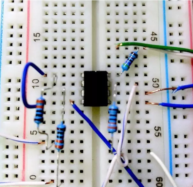
The center chip is the comparator, the interfaces are:
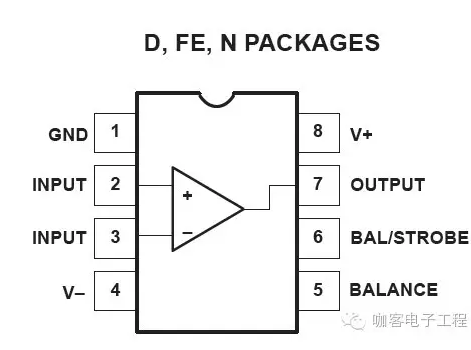
Connect the cables according to the following topology. There is a three-segment potentiometer between the ports 5 and 6, and the midpoint between them forms feedback with the output. R3 is the load.
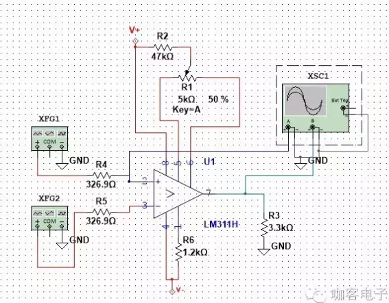
As shown, when using an amplifier, the feedback state will be positive.This feature is highly non-linear, and forming the base of the voltage comparator and Schmitt trigger circuitOf course, if I use a network of nonlinear components, such as the use of diodes, analog switches, the circuit can also run non-linearly. Common applications are precision rectifiers ah, peak-detection sample and hold amplifier ah, what's the. Or I use the BJT tube index predictability, to achieve a variety of nonlinear transfer process,In the future we will discuss in detail. Common applications include precision rectifiers, peak detect and hold amplifiers and etc. Or I can use BJT tube index predictable model to achieve a variety of nonlinear transfer process.We can discuss this later.
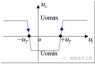
Observed the graph above, the voltage curve VTC drops quickly some time (black box) at –UT.This indicates that the gain of the device almost instantaneously infinite.In fact, the gain can not be unlimited. Only a large number, like 3 rd power of 10 or 6 th power of 10.Of course, the digital architecture requires that the comparator output states to be VoL = 0V VoH = 5V
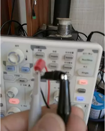
After testing the output of the signal generator, we power on this circuit. I used a diode to limit the current direction of the supply power, resulting in a voltage drop. It does not matter, we use two signal generators to output one sine signal and one higher frequency ramp signal respectively.It should be noted that the “response time “is the important parameters to judge the comparator.
Related Technical Article
- Popular Features of Current Oscilloscopes
- Why is the measured amplitude less than the real value?
- Introduction of comparator Part I
- What does oscilloscope consist of?
- Differences between oscilloscope and multimeter
- How does oscilloscope probe work?
- Common Communication Interface Guide
- Why is the measured amplitude less than the real value?
- Why should you choose a suitable scale on test and measurement equipment?
- Use your oscilloscope to decode communication protocols
